VTOR Configuration on the STM32H755ZI
Overview
In the last post (https://mab-labs.com/blog/setting-up-vs-code-for-stm32h755zi-debugging-on-macos), I showed how to set up VS Code on macOS to compile and debug an application on the M4 of the MCU. We were able to hit the `main()` breakpoint on the Coretx-M7 of the MCU. As I mentioned in the previous post, the STM32H755ZI has two ARM cores: a Cortex-M7 and a Cortex-M4. The two cores share the same flash, peripherals, and clock tree. When the MCU comes out of reset, both cores wake up simultaneously. If we’re only running code on the M7, we don’t need to be concerned about the M4; it’s effectively invisible to the M7. However, the moment we want to run an application on the M4, we need to manage the bring-up sequence. In this blog post, I will clarify how the VTOR and vector table play important roles.
The Vector Table Offset Register (VTOR)
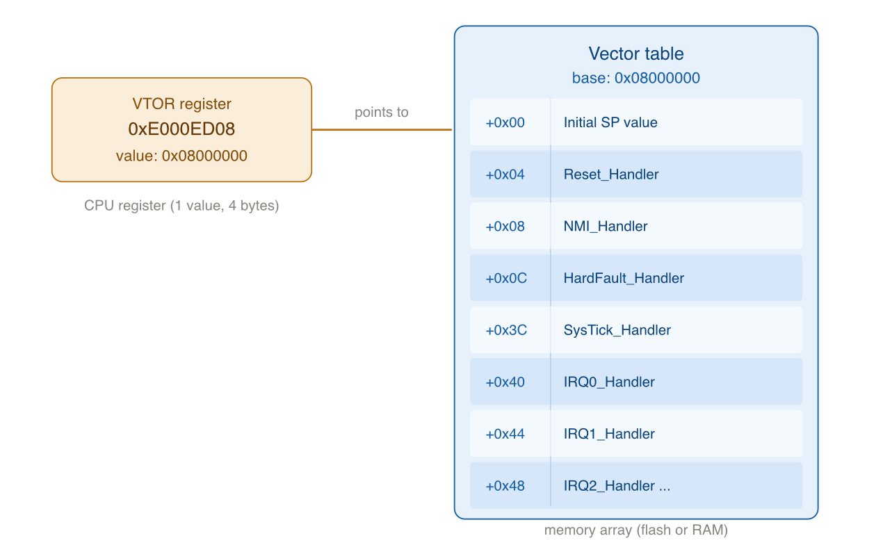
On ARM Cortex-M processors, the vector table offset register (VTOR) is an array of 32-bit addresses stored at a fixed memory location. The VTOR is the first thing the Cortex-M processor reads when coming out of reset, and it contains a few important pieces of information:
The stack pointer: The first entry in the VTOR, at offset 0, contains the value loaded into the stack pointer (SP) register before any code executes. The processor uses the SP to determine the stack's starting location.
Exception and interrupt handler addresses: Each subsequent entry in the VTOR is a function pointer to the relevant handler, which is generally required by firmware applications. For example, offset 4 is the Reset Handler, which is the entry point for our firmware. Offset 8 is the Non-Maskable Interrupt handler, offset 12 is the HardFault handler, and so on. The VTOR contains all Cortex-M exception handlers and chip-specific peripheral interrupts (e.g., UART, DMA, timers, etc.).
When an interrupt fires, the processor looks up the handler address in the VTOR at a fixed offset for that interrupt number and jumps to it. This is entirely a hardware process with no software involvement. If the VTOR contains the wrong address for a given interrupt, the core will jump to an invalid location and usually hard-fault.
One thing to keep in mind is the difference between the VTOR and the vector table itself. The VTOR is a register that contains a memory address of the table itself, and the table contains the addresses for the relevant function handlers, as shown below (Note: The image is AI-generated):
On a single-core chip, the vector table sits at the start of flash (usually at `0x8000000` on ARM Cortex-M processors), and you, as the firmware developer, rarely have to think about this. However, on a dual-core chip like the STM32H755, each core needs its own vector table with its own set of handler addresses. For example, the M7’s UART interrupt handler will obviously not be the same as the M4’s. Thus, they need different vector tables.
Diving into the code
Let’s look at the code to understand how the different vector tables are handled for the different cores. The STM32H755 has two 1MB flash banks. Nominally, bank 1, which starts at `0x8000000`, belongs to the M7, and bank 2, which starts at `0x8100000`, belongs to the M4. Each core has its own linker script that defines these boundaries. For example, the following is a portion of the M4’s linker script, which shows this memory definition:
/* stm32h755xx_flash_CM4.ld */
MEMORY
{
  FLASH (rx)   : ORIGIN = 0x08100000, LENGTH = 1024K
  RAM (xrw)    : ORIGIN = 0x10000000, LENGTH = 288K
  RAM_D2 (xrw) : ORIGIN = 0x30000000, LENGTH = 288K
}
The following is a portion of the M7’s linker script:
/* stm32h755xx_flash_CM7.ld */
MEMORY
{
  FLASH (rx)    : ORIGIN = 0x08000000, LENGTH = 1024K
  DTCMRAM (xrw) : ORIGIN = 0x20000000, LENGTH = 128K
  RAM_D1 (xrw)  : ORIGIN = 0x24000000, LENGTH = 512K
  RAM_D2 (xrw)  : ORIGIN = 0x30000000, LENGTH = 288K
  ITCMRAM (xrw) : ORIGIN = 0x00000000, LENGTH = 64K
}
The M4’s linker script also places the vector table at the beginning of bank 2:
.isr_vector :
{
    . = ALIGN(4);
    KEEP(*(.isr_vector))
    . = ALIGN(4);
} >FLASH
This means that the M4’s vector table resides at `0x08100000`.
Now that we’ve specified where the vector table belongs, how do we “tell” the two cores where to find them in memory. After a reset, both cores default to looking at address `0x00000000`, which is aliased to flash bank 1 (`0x08000000`) on the M7. This is fine for the M7, since this is the default location that the M7 searches. However, for the M4, the vector table is in bank 2. Thus, we need to set the value of the VTOR register to `0x08100000` before any interrupt fires.
This happens in the `SystemInit` function, which executes before `main()`. STM provides a shared system file that manages both cores using conditional compilation:
/* system_stm32h7xx_dualcore_boot_cm4_cm7.c */

#if defined(CORE_CM4)
  #define VECT_TAB_BASE_ADDRESS   FLASH_BANK2_BASE  /* 0x08100000 */
  #define VECT_TAB_OFFSET         0x00000000U
#elif defined(CORE_CM7)
  #define VECT_TAB_BASE_ADDRESS   FLASH_BANK1_BASE  /* 0x08000000 */
  #define VECT_TAB_OFFSET         0x00000000U
#endif

void SystemInit(void)
{
    /* ... FPU enable, cache config ... */

#if defined(USER_VECT_TAB_ADDRESS)
    SCB->VTOR = VECT_TAB_BASE_ADDRESS | VECT_TAB_OFFSET;
#endif
The `CORE_CM4`, `CORE_CM7`, and `USER_VECT_TAB_ADDRESS` macros are defined in the CMake build system:
set(M4_DEFINITIONS
    ${MX_Defines_Syms}
    CORE_CM4
    USER_VECT_TAB_ADDRESS
    VECT_TAB_BASE_ADDRESS=0x08100000
    VECT_TAB_OFFSET=0x0
)
If we forget to define `USER_VECT_TAB_ADDRESS`, the `SCB->VTOR` write is skipped entirely. The M4 will try to use the M7's vector table, and every interrupt will jump to the wrong handler. This typically manifests as a HardFault immediately after enabling any peripheral interrupt. Thus, if we’re on a dual-core ARM chip and keep hitting a HardFault handler on the “smaller” core, one of the first things we can do is ensure our VTOR is correctly set.
To understand why the VTOR must be configured so early, it helps to trace the M4’s startup sequence. The startup assembly listing (`startup_stm32h755xx_CM4.s`) defines the `Reset_Handler` function, which is the very first function that executes when the core comes out of reset:
The `Reset_Handler` function is executed from hardware (defined in the vector table at offset 4)
`SystemInit()` is called, where `SCB->VTOR` gets set to `0x08100000`.
Initialized data is copied from flash to RAM (i.e., the `.data` section).
Uninitialized data is zeroed out (i.e., the `.bss` section).
C++ static constructors are called (if our firmware is written in C++).
`main()` is called
The critical ordering here is that `SystemInit()` runs before any data initialization. This means VTOR is configured before the first interrupt could possibly fire, which is exactly what we want. If an interrupt fires before VTOR is set, the core will jump to whatever address is in the M7's vector table at that interrupt's offset, which is not what we want.
In the next post, I will demonstrate how we can ensure that the different cores are sequenced correctly.